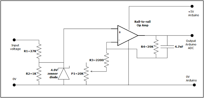
Arduino data logger - Voltage measurementMost of the time the voltage will be held to around 12V by the battery, however, if the battery is disconnected the voltage in the circuit can rise much higher. I wanted a means of isolating the Arduino from any voltage over 5V. Initially, I experimented with a simple voltage divider with a 4.8 volt zenner diode across the Arduino input to control any over voltage. This worked to a point, but the zenner diode did not have a clean cut off point and voltage went off the linear well before 4.8 volts. In the end I simply used a voltage divider to drop the input voltage to a low value (approx 1/28 of the input) and then the same MPC6283 rail-to-rail op amp used in the current measurement to amplify the signal back to the required value. When the input voltage goes out of range the op amp is saturated but the voltage into the ADC does not exceed 5V. The circuit used is: 
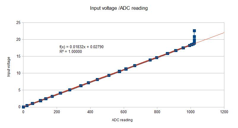
CalibrationIt is quite easy to apply a voltage near to the maximum across the sensor using some batteries and then adjust the gain so the ADC value is around the maximum value of 1023. (I used several 9V cells clipped together with a potentiometer as a voltage divider as a source). I plotted a graph of voltage against ADC value and deliberately went over scale to check the linear range. The trend line is calculated from just the linear portion of graph. 
|