
Arduino data logger - Wind speed measurementThe anemometer sensor is home made from a small triangle of plywood with 3 cups (half a table tennis ball) glued to the ends. A single small ball race is held in the centre on a long bolt and the outside is pushed into a hole in the centre of the plywood. This allows the rotor to rotate very freely and it seems to follow the wind speed quite closely. A piece of broken neodymium magnet is used as the actuator. I initially tried a reed switch but this didn't work very well. There was a slight attraction between the magnet and the switch which affected the rotation of the rotor and the switch did not open or close cleanly resulting in a burst of interrupts being generated in the Arduino. This was replaced with a Hall effect switch which was much more consistent. The switch was soldered to the wires and then cast in a small disk of fibreglass resin which meant it was weather proof and could be easily bolted just below the rotor. The anemometer in the pictures below has a radius of 66mm to the edge of the cups. 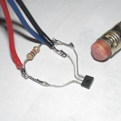 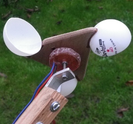 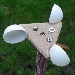 The circuit for the wind speed is very similar to the frequency measurement. The anemometer was going to be at the end of about 25m of cable so I used a separate power supply and isolated it from the Arduino board. The main components are:
The circuit diagram is: 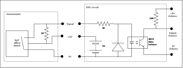 CalibrationCalibrating the wind speed has been a bit harder than the other sensors. The wind power is proportional to the wind speed cubed so a small error in the wind speed has a large effect on the power and efficiency calculations (e.g. a 5% error in wind speed results in 15% error in power). I first tried to use a small hand held anemometer to determine the wind speed and measured the frequency output from the the data logger anemometer with a multimeter. The anemometers were held side by side in different wind speeds and the readings were videoed so they could be compared later. Not only is this time consuming the end results are not very consistent. The second method used the data logger to measure both the rotation of the anemometer and the wind speed. I attached a light batten of wood about a metre (3 feet) long to a turbine hub and attached the anemometer to the end of the batten. The axis of rotation was along the batten so both cups will be in the same speed air flow when the hub is rotated. Each rotation of the hub moves about anemometer about 6 metres so spinning the hub at 3 times a second gives an air speed of about 18 m/s or 40 mph. The pictures show the set up used. The hub was balanced using a couple of G clamps. The wire from the anemometer passes down the centre of the axle. 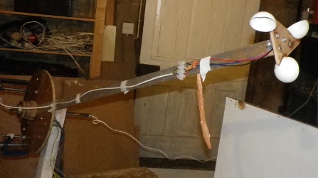 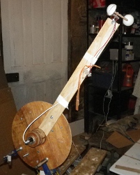 To get the readings I started the data logger and spun the hub by hand at various speeds to give a range of points. I had to periodically reverse the direction of rotation to stop the anemometer cable winding up too much. It was then simple to take the alternator rotation speed data, convert it to a speed using the length of the batten, and then plot a graph against the output from the anemometer. The data logger would not register the speed of the hub below about 30 RPM (half a rotation a second) so I used a shorter batten to get the slow speed results. The graph below shows the results from four runs. I ran a trend line through all the data points and used this as the calibration. 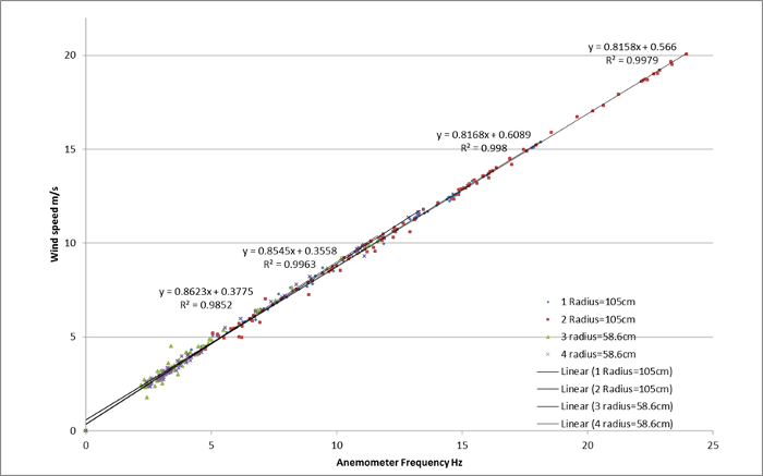 |